12 Results
View results:
Sort by:

This article compares the design to the one in the referenced article: Design of Concrete Columns Subjected to Axial Compression with RF-CONCRETE Members. It is, therefore, about taking exactly the same theoretical application carried out in RF-CONCRETE Members and reproducing it in RF-CONCRETE Columns. Thus, the objective is to compare the different input parameters and the results obtained by the two add-on modules for the design of column-like concrete members.

In RFEM, it is possible to display the resultant of a section or release. This article explains which part of the sectional area is affected. The easiest way would be to refer the resultant to a cut face of the surface. However, since a section may run through several surfaces with different local coordinate systems, determination by means of a cut face is not possible.
Since wind on laterally open structures is not addressed in the Eurocode, the 4 cases of the German DIN 1055, Part 4 are referenced.
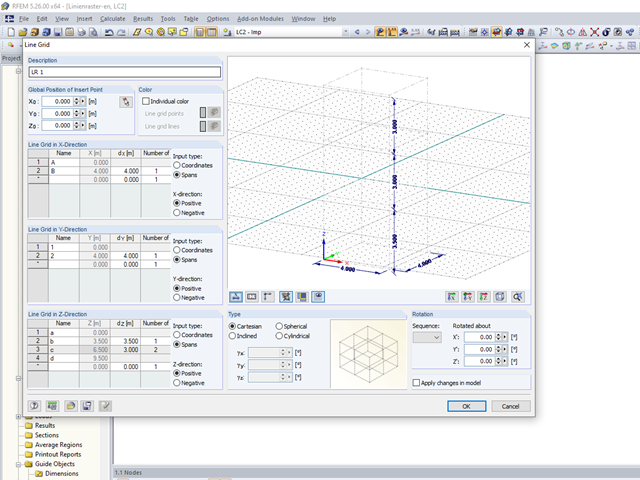
In the Formula Editor environment, you can specify any parameters (lengths, force values, and so on) to control load and geometry data in the modeling.
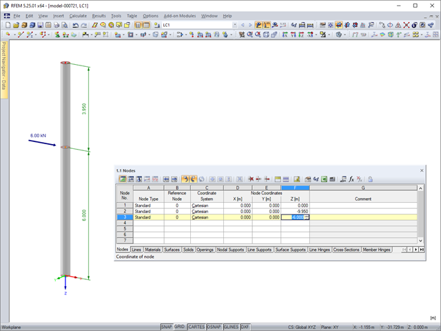
Model and load objects can be defined graphically or in tables, or they can be created using parameters (see the manual). With this parameterized input, you can also access the cells of certain tables of the program. In this way, it is possible to link a load parameter with a model data parameter, for example. The reference is created by the $ sign.
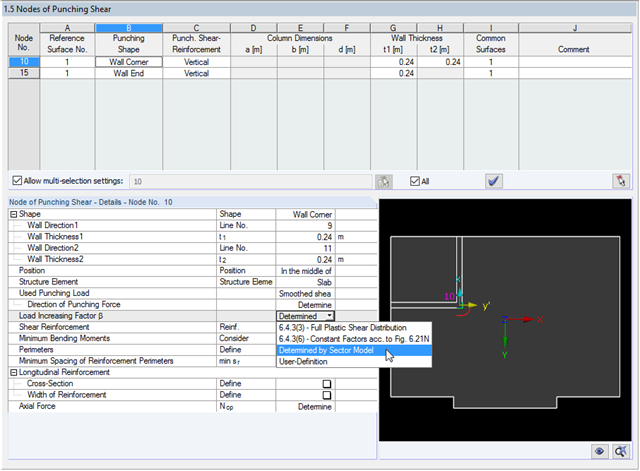
The RF-PUNCH Pro add-on module allows you to perform punching shear designs according to EN 1992‑1‑1 [1]. In addition to the design checks of single columns, wall ends and wall corners can be analyzed in RF‑PUNCH Pro. At this point, I would also like to reference a previous article about RF‑PUNCH Pro, which explains how to determine punching load on wall ends and wall corners.
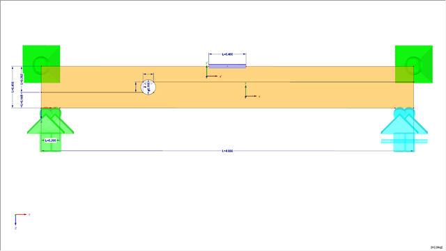
This article presents a bending beam with a circular opening analyzed using the numerical method. As a reference point, there is an example of a perforated beam from [1]. In our case, the 3D model was simplified to a two-dimensional discretization.
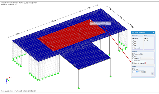
In RFEM and RSTAB, you can add user‑defined dimension lines to a structural model. When creating these dimension lines, click the objects (for example, end nodes of a line, members, and so on) that represent the reference points of the dimension. If you want to add a dimension line free from the structure previously defined in the model, you have to create an additional free "help node" that acts as a reference object for the new dimension.
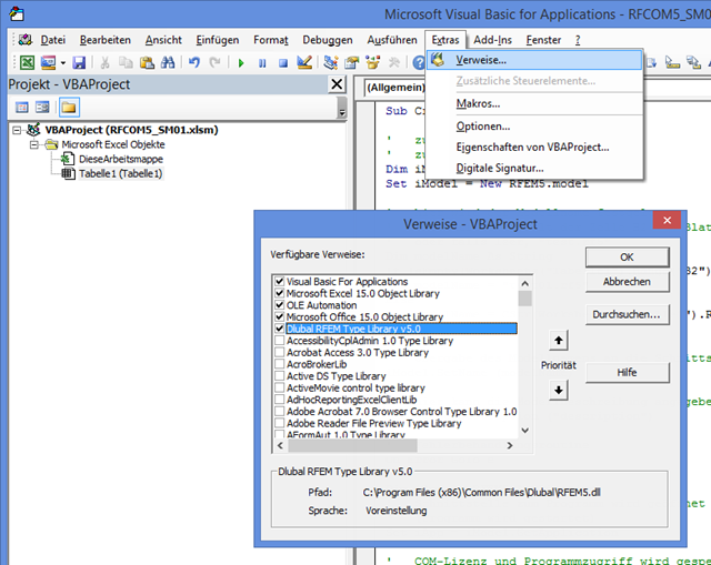
The first part of the post about the COM interface describes opening and closing RFEM. VBA programming language is used in Excel; however, the program sequence is the same as for programming with C#. First, it is necessary to add the corresponding reference in VBA to recognize the commands for the interface. The image on the left shows an example of RFEM 5.
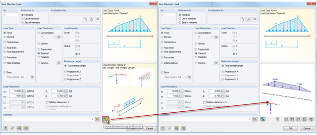
In addition to the load direction and reference length of member loads, it is now possible to display a preview of the loading.
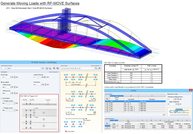
Moving loads can be generated easily with RF‑MOVE Surfaces. A library is available with load models as defined in Eurocode 1, Part 2. The input of step size, offsets at start and end, and the distance to a reference line make it possible for the user to generate user‑defined load models and influence the number of load cases generated. RF‑MOVE Surfaces generates load cases and, optionally, a result combination as an envelope of all results.
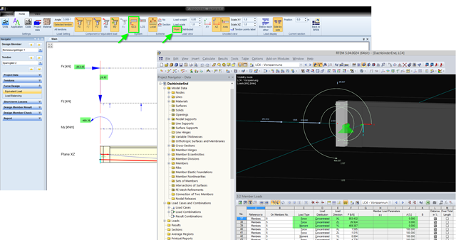
The equivalent loads determined in RF-TENDON due to prestress are transferred in RFEM as member loads or as line loads. A member load is used for member types with their own stiffness; a line load is used for member types without their own stiffness. In order to understand which values of the concentrated loads are to be transferred from RF‑TENDON to RFEM, you should use the following display settings: ~ Reference of the loads to the global coordinate system (GCS), ~ Load display: "Point"